Upgrade & Secure Your Future with DevOps, SRE, DevSecOps, MLOps!
We spend hours scrolling social media and waste money on things we forget, but won’t spend 30 minutes a day earning certifications that can change our lives.
Master in DevOps, SRE, DevSecOps & MLOps by DevOps School!
Learn from Guru Rajesh Kumar and double your salary in just one year.
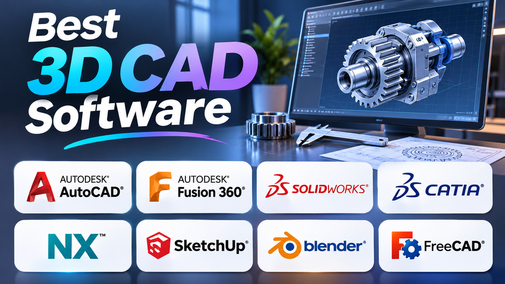
A 3D CAD model can begin as a simple sketch and end as a manufactured component, a detailed architectural model, or a complex engineered assembly. The software behind that process determines more than how the model looks. It affects how easily dimensions can be changed, how teams collaborate, how designs move into manufacturing, and how much time engineers spend managing files.
The challenge is that 3D CAD software is not one uniform category. A mechanical engineer designing a precision gearbox has different requirements from an architect creating a building concept or a hobbyist preparing a component for 3D printing. A tool that works well for one workflow may introduce unnecessary cost or complexity into another.
This guide examines eight established options, from integrated commercial platforms to open-source modeling tools, and explains which design situations each one suits.
What makes 3D CAD software different?
Computer-aided design software helps users create, modify, document, and communicate digital representations of physical objects or systems. Depending on the application, it may support parametric modeling, assemblies, technical drawings, simulation, rendering, or manufacturing preparation.
Three modeling approaches are particularly important when choosing a tool.
- Parametric modeling: Features are built around dimensions, constraints, and a sequence of operations. Changing a dimension can update dependent features throughout the model. This is valuable when designs must evolve through engineering revisions.
- Direct modeling: Geometry can be modified more directly without relying entirely on an existing feature history. It can be useful when editing imported models or making quick changes to unfamiliar geometry.
- Surface and freeform modeling: These approaches help create complex curves and organic shapes, particularly for industrial design, product styling, and components where appearance matters alongside function.
Many applications combine more than one approach. The practical difference is how well each tool supports your team’s actual modeling process.
Eight 3D CAD tools and the workflows they support
1. Autodesk Fusion — for connected design and manufacturing
Autodesk Fusion combines 3D design with capabilities for manufacturing, engineering analysis, electronics design, and collaborative product development. Its connected environment is useful when a team wants to move from a modeled component to drawings and manufacturing preparation without managing every stage in a separate application. Autodesk+1
The platform supports parametric, direct, surface, mesh, and freeform modeling. That range helps when a workflow involves both dimension-driven mechanical components and imported or scanned geometry. Manufacturing tools are especially relevant for teams that also need to prepare CNC machining operations.
Where it fits: Product designers, mechanical engineers, prototyping teams, small manufacturers, and businesses that want design and manufacturing workflows in one connected environment.
What to consider: Fusion is cloud-connected, even though it runs as a desktop application. Before adopting it, evaluate connectivity requirements, data-management practices, subscription terms, and how your organization will manage access to project files. Advanced capabilities may depend on the selected plan or extensions.
Official product information: Autodesk Fusion
2. SOLIDWORKS — for mechanical design and engineering documentation
SOLIDWORKS is a well-established option for engineering teams focused on mechanical parts, assemblies, and manufacturing drawings. Its feature-based modeling approach supports designs that must be revised repeatedly as dimensions, component relationships, and engineering requirements change.
For example, a team designing a pump assembly may need to update a housing, verify how related components fit together, and produce drawings for manufacturing. A mechanical CAD workflow built around editable features and assemblies is well suited to this type of work.
Where it fits: Mechanical engineering departments, industrial equipment manufacturers, product development teams, and organizations whose design processes depend on detailed engineering documentation.
What to consider: The overall cost is not limited to software licensing. Training, hardware, compatible file formats, data management, and collaboration arrangements can all affect implementation. Check the precise edition and licensing arrangement against the features and deployment model your team needs.
Official product information: SOLIDWORKS
3. CATIA — for complex products and multidisciplinary engineering
CATIA is designed for advanced product engineering, including complex surface modeling and multidisciplinary design workflows. It is relevant when a product contains many interdependent parts, sophisticated geometry, and demanding coordination across engineering disciplines.
In industries such as aerospace and automotive engineering, teams may need to work with intricate surfaces and large product structures while maintaining design consistency. CATIA’s role in these environments is broader than simply creating a three-dimensional shape; it can form part of a larger product-development process.
Where it fits: Organizations developing complex industrial products, particularly where advanced surfacing, large assemblies, and coordinated engineering workflows are central requirements.
What to consider: CATIA may be more capability than a small team needs for straightforward parts or basic 3D printing. Assess training requirements, existing engineering processes, data compatibility, and the specific CATIA configuration being offered before committing.
Official product information: CATIA
4. Siemens NX, now known as Designcenter — for advanced product engineering
Siemens’ former NX CAD product family is now presented under the Designcenter name. It targets multidisciplinary product engineering and supports demanding design workflows involving complex geometry, engineering data, and connected product-development processes. Siemens
Its relevance becomes clearer when a company must coordinate detailed part design with broader engineering requirements rather than produce isolated models. Organizations evaluating it should consider how it fits into their existing manufacturing, simulation, and product-data systems.
Where it fits: Advanced engineering organizations, complex product development, and teams that need a broader engineering environment.
What to consider: Confirm the current product name, available configuration, licensing, deployment model, and interoperability with existing tools. Siemens’ transition from the NX naming convention to Designcenter also makes it important to verify product documentation and procurement terminology carefully.
Official product information: Siemens Designcenter CAD
5. FreeCAD — for open-source parametric modeling
FreeCAD is a free, open-source parametric 3D modeler for mechanical design, prototyping, technical drawings, and other engineering tasks. It supports Windows, macOS, and Linux, and works with formats including STEP, IGES, STL, and DXF. FreeCAD+1
Its open-source licensing is a meaningful advantage for individuals, educators, small workshops, and organizations that want to avoid mandatory commercial software subscriptions. The parametric approach also lets users revisit model history and adjust design parameters rather than rebuilding every part from scratch.
Where it fits: Budget-conscious designers, engineering students, makers, 3D-printing enthusiasts, and teams that value open formats and software extensibility.
What to consider: An open-source tool still requires a practical evaluation. Check whether the available workbenches, documentation, drawing tools, collaboration process, and model compatibility meet your specific engineering requirements. If a business depends on specialist commercial workflows, test representative projects before making FreeCAD the primary production tool.
Official project website: FreeCAD
6. SketchUp — for architectural and spatial modeling
SketchUp is particularly useful for quickly creating and communicating spatial concepts. Architects, interior designers, builders, and other design professionals can use it to explore layouts, volumes, furniture arrangements, and building concepts.
Its appeal is the ability to move from an idea to a recognizable three-dimensional representation without beginning with a highly detailed mechanical engineering workflow. For early design conversations, a clear spatial model can be more useful than a fully constrained mechanical component.
Where it fits: Architectural concept development, interior design, spatial planning, and visual communication.
What to consider: SketchUp is not a direct substitute for every mechanical CAD system. If your work depends on detailed parametric part histories, complex mechanical assemblies, or manufacturing drawings with engineering constraints, verify that the required capabilities are available in your chosen workflow.
Official product information: SketchUp
7. Blender — for visual modeling rather than engineering-first CAD
Blender is a powerful open-source 3D creation application used for modeling, rendering, animation, and visual content. It can be useful when the primary objective is to create compelling visuals of a product, explore artistic forms, or produce presentations and animations.
However, Blender should not automatically be treated as interchangeable with a parametric engineering CAD system. A visually convincing object is not necessarily a dimensionally constrained, editable engineering model ready for a manufacturing process.
Where it fits: Product visualization, design presentations, animation, creative modeling, and workflows in which appearance is the main priority.
What to consider: If you need precise dimensional relationships, engineering drawings, or a history of editable manufacturing features, test the exact workflow carefully. Blender may complement a CAD tool rather than replace it.
Official product information: Blender
8. Autodesk AutoCAD — for established 2D drafting and related design workflows
AutoCAD is widely associated with technical drafting and documentation. It supports 2D drafting and also provides 3D modeling capabilities, making it relevant to workflows that involve existing CAD drawings, layouts, and technical documentation.
For organizations with established drawing libraries, AutoCAD can be important because the challenge is often not just creating new geometry but maintaining consistency with existing documentation and exchanging drawings with other stakeholders.
Where it fits: Drafting teams, technical documentation, layout work, and organizations that rely on DWG-based drawing workflows.
What to consider: If your central task is managing a complex parametric mechanical assembly or integrating design with CNC manufacturing, compare AutoCAD with a product-development platform designed specifically for that process. A familiar drafting tool may not be the most efficient primary environment for every 3D engineering project.
Official product information: Autodesk AutoCAD
Comparing the tools by practical use case
The following table is intended to clarify each tool’s general role, not to establish a universal ranking.
| Software | Primary strength | A sensible starting point for | Main consideration |
|---|---|---|---|
| Autodesk Fusion | Connected CAD, CAM, CAE, and product development | Prototyping and manufacturing-oriented design | Cloud connectivity, plan scope, and data management |
| SOLIDWORKS | Mechanical parts, assemblies, and drawings | Mechanical engineering teams | Licensing, training, and existing workflows |
| CATIA | Complex surfaces and multidisciplinary product engineering | Advanced industrial product development | Implementation complexity and specialist training |
| Designcenter (formerly NX CAD) | Advanced product engineering | Complex engineering organizations | Configuration, deployment, and ecosystem fit |
| FreeCAD | Open-source parametric modeling | Learning, prototyping, and cost-conscious design | Workflow fit and required workbenches |
| SketchUp | Fast spatial and architectural modeling | Architecture and interior design | Engineering constraints and manufacturing needs |
| Blender | Visual modeling, rendering, and animation | Product visualization and creative work | Not a conventional engineering-first CAD workflow |
| AutoCAD | Drafting and technical documentation | Drawing-centered design processes | May not suit every complex 3D product workflow |
The decisions that matter before you choose
A long feature list can make two CAD products appear similar even when they support different working methods. A more reliable evaluation starts with the work your team actually performs.
Decide what the model must do
Start by identifying the expected output.
If the result must be manufactured, check dimensional control, tolerances, drawings, assembly relationships, and the handoff to production. If the result is intended for a presentation, rendering quality and ease of visual iteration may matter more. If the goal is architectural planning, spatial modeling and the ability to communicate layouts may take priority.
Do not pay for advanced engineering capabilities if the project does not require them. Equally, do not select a visualization tool for an engineering process that depends on precise, editable design data.
Test design changes, not just the first model
Most CAD demonstrations focus on creating an object. Real engineering work also involves changing it.
Use a representative test project and modify a critical dimension after building several dependent features. Check whether the model updates predictably, whether downstream components remain valid, and how easily you can understand the design history.
For an assembly, change a component that affects the fit of other parts. Observe whether the tool helps you identify dependent geometry and revise the design without rebuilding unrelated work.
These tests reveal more about day-to-day suitability than a demonstration of how quickly a basic shape can be created.
Verify file exchange before committing
CAD files do not always preserve the same information when transferred between applications. A neutral geometry format may transfer a solid shape successfully while losing the original feature history or other editable design information.
Before selecting software, test the file types your customers, suppliers, manufacturers, and colleagues actually use. For example:
- STEP is commonly used to exchange 3D product geometry between CAD systems.
- IGES is another established format for exchanging geometric data.
- STL is commonly used for 3D-printing workflows, but it represents surface geometry rather than the complete parametric feature history of a CAD model.
- DXF and DWG are important to many 2D drafting and drawing-exchange workflows.
Do not assume that opening a file guarantees a perfect transfer. Test a real part or assembly, inspect its geometry and dimensions, and confirm whether the receiving system can make the changes your workflow requires.
Calculate the full cost of ownership
The subscription or license fee is only one part of the cost of CAD software. Consider the complete working environment.
- Training: How long will users need to become productive with the modeling approach?
- Hardware: Will your typical assemblies and models run comfortably on the available computers?
- Extensions: Are essential functions included, or do they require separate modules or plans?
- Data management: How will you handle versions, permissions, backups, and project ownership?
- Collaboration: Can internal teams and external suppliers work with the chosen file formats and review processes?
- Migration: How much effort would be required to move existing models, drawings, and established workflows?
For an individual designer, a free tool may be the most economical option. For a production team, a commercial platform that fits existing processes may justify its cost. The important comparison is the cost of completing the full workflow, not the license price in isolation.
Common mistakes when evaluating 3D CAD software
Choosing based on appearance alone. An attractive interface or realistic rendering does not establish whether the software can manage constrained geometry, complex assemblies, or manufacturing documentation.
Assuming every 3D application is CAD. Polygon modeling, visualization, architectural modeling, and parametric engineering overlap, but they are not the same discipline. Select the tool according to the required output and design process.
Ignoring existing files and suppliers. A technically capable tool can still create friction if customers or manufacturing partners cannot work efficiently with its deliverables.
Overlooking licensing conditions. Free access may be limited by usage terms, feature availability, or organizational requirements. Commercial subscriptions may also vary by edition and included capabilities. Read the current terms for the exact plan before making a decision.
Skipping a realistic pilot. A small demonstration project rarely exposes problems with large assemblies, revision management, file exchange, or production handoff. Test representative work before migrating an entire team.
A practical selection framework
Use the following starting points to narrow the options:
- You need a connected design-to-manufacturing workflow: Begin by evaluating Autodesk Fusion.
- Your work centers on mechanical components and detailed engineering drawings: Evaluate SOLIDWORKS alongside other mechanical CAD systems that fit your industry’s requirements.
- You develop highly complex industrial products or advanced surfaces: Consider CATIA or Siemens Designcenter.
- You want open-source parametric CAD without a mandatory commercial subscription: Start with FreeCAD.
- You mainly model buildings, rooms, or spatial concepts: Evaluate SketchUp.
- You primarily create rendered product visuals or animated presentations: Consider Blender as a visualization tool, potentially alongside an engineering CAD application.
- Your workflow revolves around technical drawings and existing CAD documentation: Assess AutoCAD and confirm whether its 3D capabilities match your specific needs.
These are starting points rather than absolute recommendations. Product editions, licensing arrangements, and capabilities differ, so verify the current offering before making a purchasing decision.
Questions to answer during a software trial
Before choosing a platform, ask your team to complete a short, realistic pilot and answer these questions:
- Can we model a representative part with the dimensional constraints we need?
- Can we revise important dimensions without introducing unexpected errors?
- Can we assemble related components and inspect their relationships?
- Can we produce the drawings, exports, or visual outputs required by our workflow?
- Can we exchange files with our suppliers and customers without losing essential information?
- Can our available hardware handle projects of the expected size?
- Do the license terms, training requirements, and data-management arrangements suit our organization?
The answers provide a defensible basis for choosing software instead of relying on popularity or a generic feature comparison.
Make the workflow the deciding factor
The right 3D CAD application is the one that supports the work from the first sketch to the required final deliverable. Autodesk Fusion and SOLIDWORKS are relevant starting points for many product-design and mechanical workflows; CATIA and Designcenter address more demanding engineering environments; FreeCAD offers an open-source route; and SketchUp, Blender, and AutoCAD serve different modeling and documentation priorities.
Before investing in a platform, take one representative project through modeling, revision, file exchange, and final output. That single exercise will often reveal whether a tool fits your actual requirements—and whether you need one application or a combination of complementary tools.
